‘The step serves a dual purpose:
(1) Once the aircraft begins to hydroplane, the surface area in contact with the water reduces substantially, further reducing the hydrodynamic drag.
(2) Once near liftoff speed, the step allows the aircraft to rotate to lift off.’
– General Aviation Aircraft Design: Applied Methods and Procedures by Snorri Gudmundsson.
This photo, taken by Frank Herbert, is of Waterbird taking off. It depicts the operation of the stepped float as to the extent to which it is in contact with the surface.
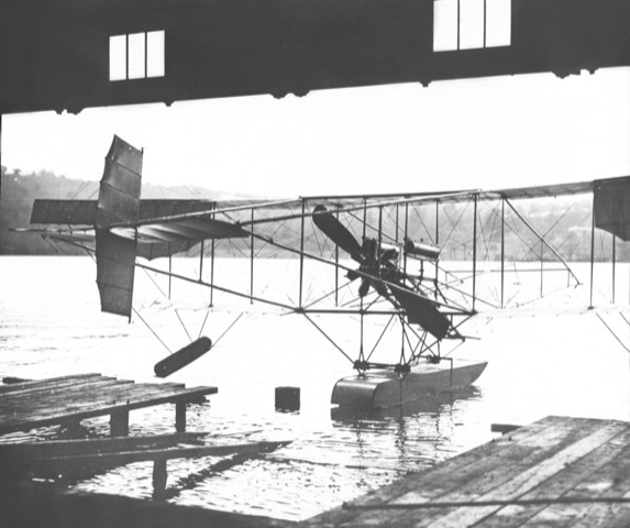
On 25 November 1911, at Windermere, Waterbird made the first successful flight in the world to use a stepped float, only achieved by embodying Edward Wakefield‘s 2 years of considerable experiments with floats of many shapes and sizes. The pilot was Herbert Stanley Adams. Adams confirmed the initial flights to Wakefield by telegram.
Built by A. V. Roe & Company at Manchester, the landplane was delivered to Windermere following flight-testing at Brooklands on 7 July 1911 for conversion to a hydro-aeroplane.
The central float and auxiliary wingtip floats, were made by Borwick & Sons, boat builders of Bowness-on-Windermere, who also made floats for Oscar Gnosspelius.
The dimensions of the float followed those used by Glenn Curtiss. ‘We changed the floats and finally made one long, flat-bottomed, scow-shaped float, twelve feet long, two feet wide, and twelve inches deep’. – The Curtiss Aviation Book.
Curtiss’s pontoon ‘is twelve feet long, two feet wide and twelve inches deep’. – Scientific American magazine, 25 February 1911.
‘Waterbird’s main float is 12 ft. long, 2 ft. wide, with a depth of 1ft.’ – The Aeroplane magazine, 25 January 1912.
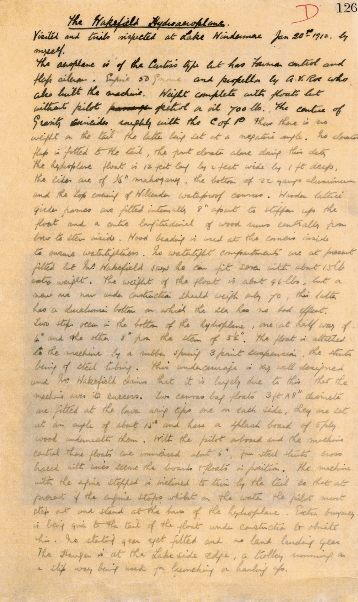
On 20 January 1912, Waterbird was test-flown for the Royal Navy by Lieutenant Arthur Longmore. In his Report, he described the central float:-
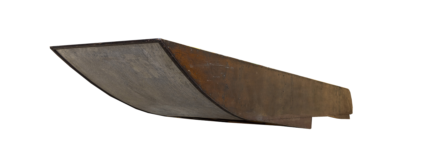
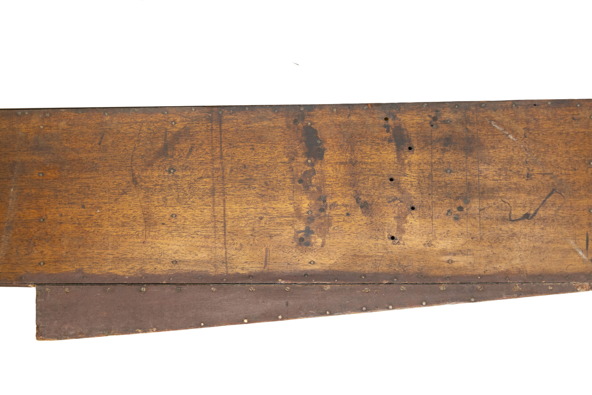
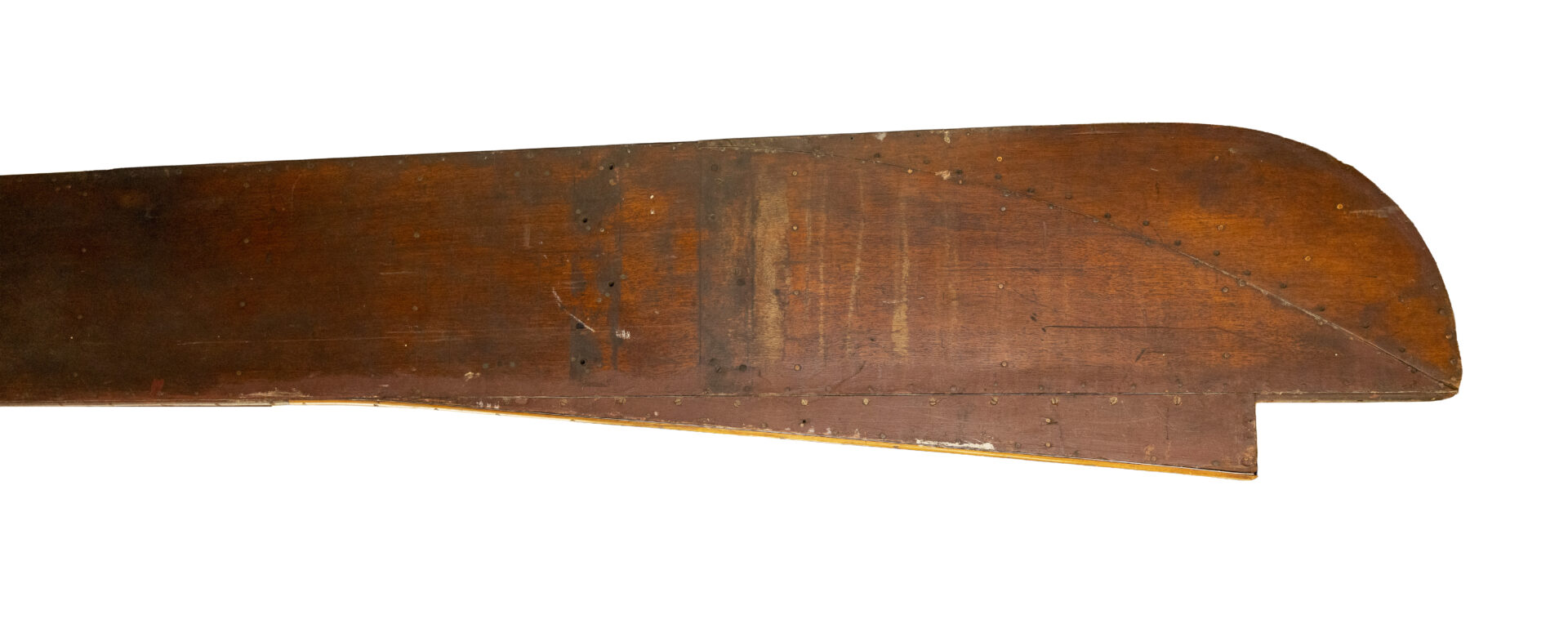
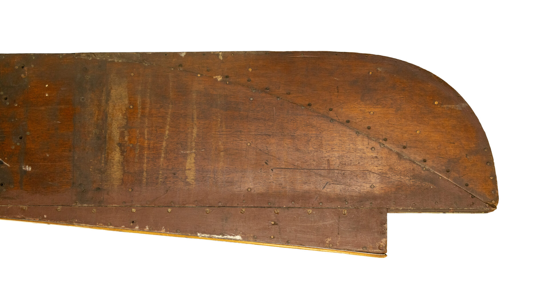
- 12 feet long by 2 feet wide by 1ft deep
- the sides are of ¼” mahogany
- bottom of 22 gauge aluminium
- wooden lattice girder frames are fitted internally 8″ apart
- *a centre longitudinal of wood runs centrally from bow to stern inside
- wood beading is used at the corners inside
- no watertight compartments are at present fitted
- two steps occur in the bottom of the hydroplane, one at halfway of 4″ and the other 8″ from the stern of 3½”.
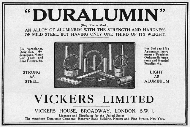
He further stated that a new float was then under construction which has a duralumin bottom.
Appraisal
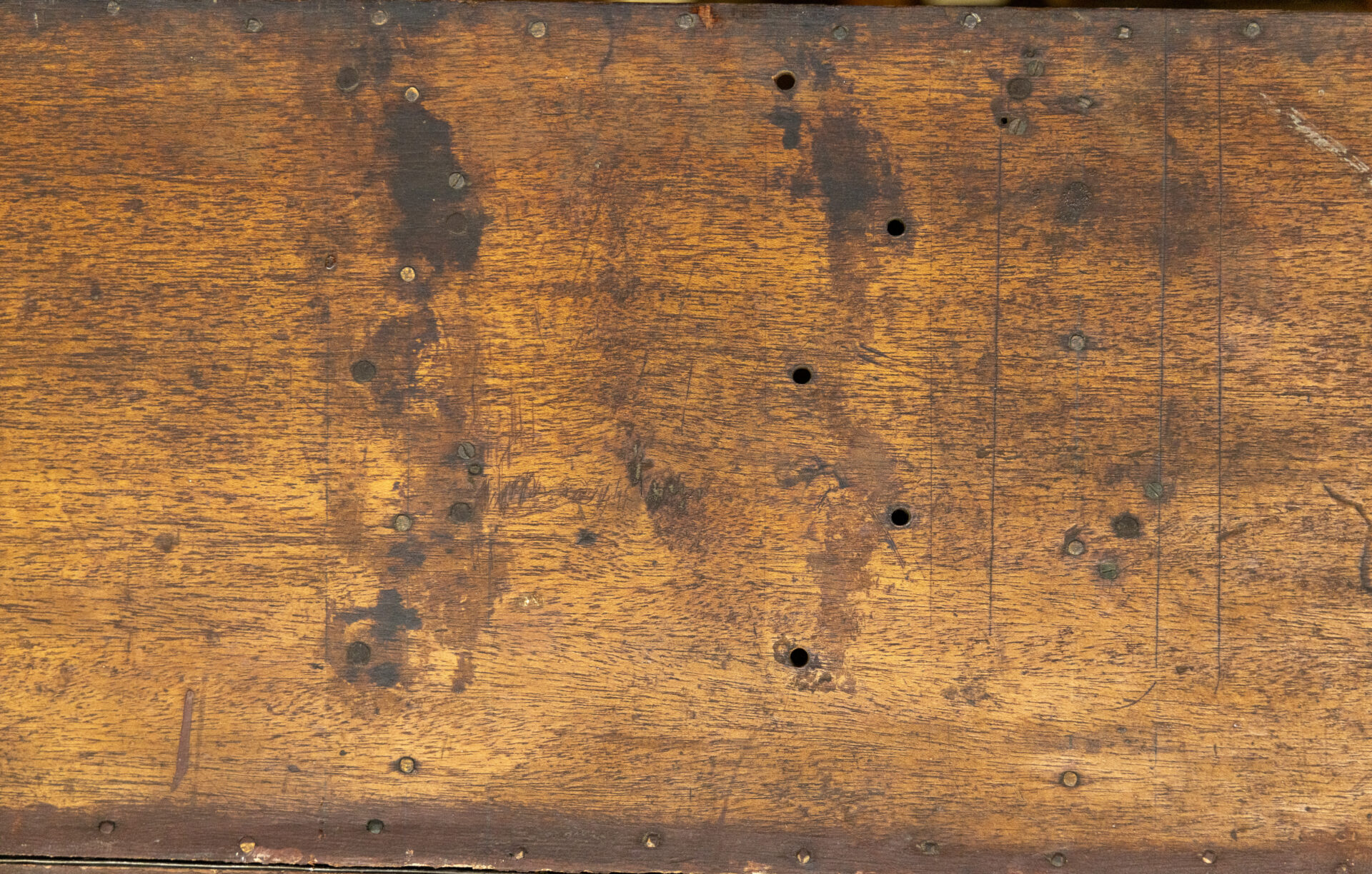
* The length of the centre longitudinal, which makes the structure stiffer and more impact resistant, cannot be verified as it is now broken at the stern end after 6 feet.
Examples of weight reduction are the use of a Willesden waterproof canvas cover and every other girder frame has no diagonals.
In September 1911 a forward step was created, but still Waterbird would not take off and in early November another step was added at the rear. Later a ‘bustle‘ was added so as to form a tapering stern and create more buoyancy.
Examination of the surviving float shows not only the above work, but also that the undercarriage connection was moved by 6 inches.
The bottom was created in a single sheet.
Analysis carried out by 1710 Naval Air Squadron determined that it is aluminium.
WHAT HAPPENED TO WATERBIRD’S CENTRAL FLOAT AND OTHER SURVIVING PARTS
James Betts, Secretary of The Northern Aircraft Company Ltd, wrote to Wakefield on 29 December 1914 ‘With regard to Waterbird’s old float, we will certainly hand it to you when we have finished with it, and will not break it up’.
In a Westmorland Gazette article of 22 March 1941, Wakefield stated ‘The first successful float hangs above my head as I write’.
On 20 April 1962, Sir Wavell Wakefield, Edward Wakefield’s nephew, wrote to the Westmorland Gazette that he still had the float, now in his garage.
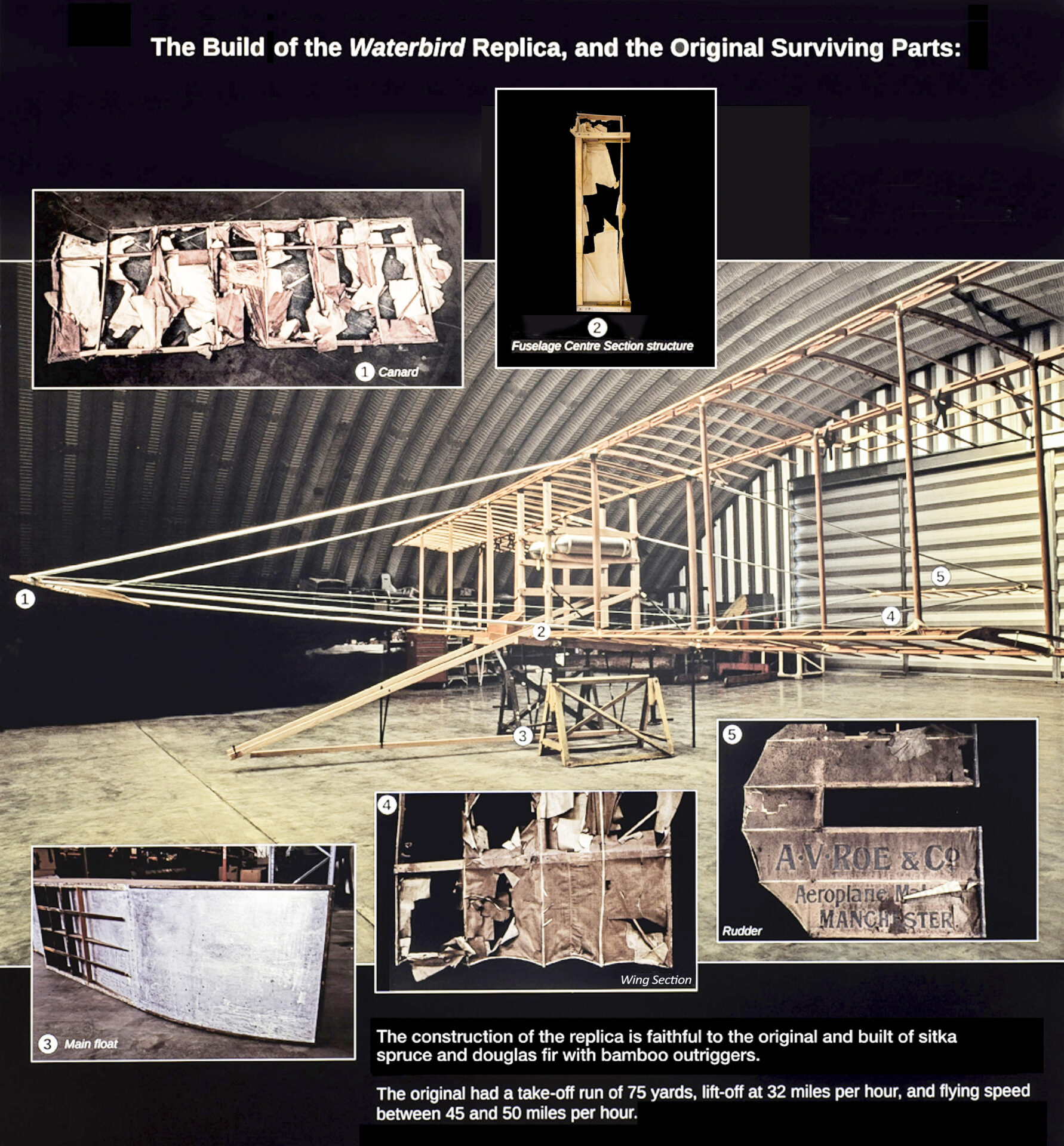
The engine was re-used in the Avro Duigan/Seabird. Other surviving parts were the canard, centre section structure of wing, port lower wingtip section, stringer from the centre section and a rudder.
On 27 July 1971, the well-preserved central float and other surviving parts were presented to the Royal Air Force Museum by Lord Wakefield. They were initially displayed at the RAF Museum, Hendon, moving to Cardington. Then, following storage at RAF Henlow, they were transferred to the RAF Museum Reserve Collection at Stafford.
In January 2022, the RAF Museum selected Waterbird’s central float and the other parts for transfer of ownership and invited expressions of interest. They are now in the Windermere Jetty Museum’s Collection.
THE WINDERMERE HISTORY IS HERE
Click image to enlarge

Flight magazine
Made with lightweight timber, the float is longitudinally-framed. That is, the structural members predominantly run forward to aft with only the 4 dividing bulkheads acting as transverse structure. – This layout was chosen to best counteract loads on the float.
The float has 5 watertight compartments and also increased buoyancy of 109% in excess of the buoyancy required to support the maximum weight of the complete aeroplane [the regulatory requirement is a minimum of 80%].
WHY WATERBIRD’S FLOAT HAD AN ALUMINIUM FLOOR
It is considered that the 22 gauge aluminium floor of Waterbird’s central float derived from airship construction at Barrow-in-Furness.
Upon his appointment in 1909 as Inspecting Captain of Airships, Murray Sueter (later Rear Admiral Sir, CB) was directed by Rear Admiral Ernest Troubridge (later Admiral Sir) to include the study of aeroplanes. He instituted a series of aeronautical lectures on HMS Hermione moored at Barrow.
A number of Royal Navy airship officers at Barrow became personally interested in the hydro-aeroplane experiments at Windermere. For example, exchange of information as to design of floats included from Windermere, whilst the Green engine of Schwann‘s Avro D – Note His Majesty’s Airship No. 1 in the background of this photo – at Barrow was only made to function after Adams had correctly re-assembled the rocker gear. Lieutenant Frederick Boothby (later Captain, CBE) designed Avro D floats, made by Vickers, Sons & Maxim Ltd (‘Vickers’). With a view to saving weight, the floats had the application of a duralumin channel bar framework [Vickers had acquired the patent from Germany in 1910] and a sheet aluminium floor.
The Agreement between Wakefield and Adams dated 20 December 1911 had a Schedule comprising an inventory of equipment at Hill of Oaks, which included 6 pieces of aluminium and duralumin. The Report on Waterbird by Longmore, dated 20 January 1912, included that a new float was intended to be fitted with a duralumin floor.
In a Report, published in the Royal Aircraft Factory Reports and Memoranda of December 1911, Sueter noted that the aluminium had suffered considerably from the action of salt water on it.
Also, Vickers took an interest in the material used by Henri Fabre and on 25 October 1910 wrote asking if he could supply them with tubing made of it at 4 inches inside diameter and 65 ½ feet long.
The float of Waterhen was described in a Flight magazine article, 7 December 1912. ‘A latticed skeleton of silver spruce having three longitudinal bulkheads. Aluminium covers the bottom, duralumin the sides, and Willesden canvas the top’.
7 samples of duralumin taken from Airship No. 1 were tested in September 1913 to determine whether any deterioration had taken place with lapse of time. The results varied between ‘surface untarnished’ to ‘considerably corroded’. – Report on Light Alloys by Dr W Rosenhain FRS.
– Waterbird ‘is undoubtedly the first really successful hydroplane in the country, and Mr. Wakefield and the manager of the company, Mr. Stanley-Adams, deserve very great credit for the work they have done’. – The Aeroplane magazine, 25 January 1912.