TECHNICAL INFORMATION
BACKGROUND
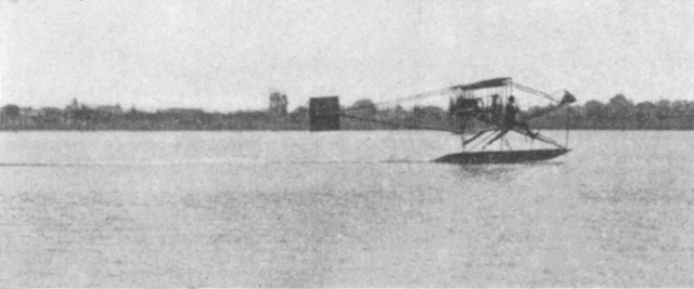
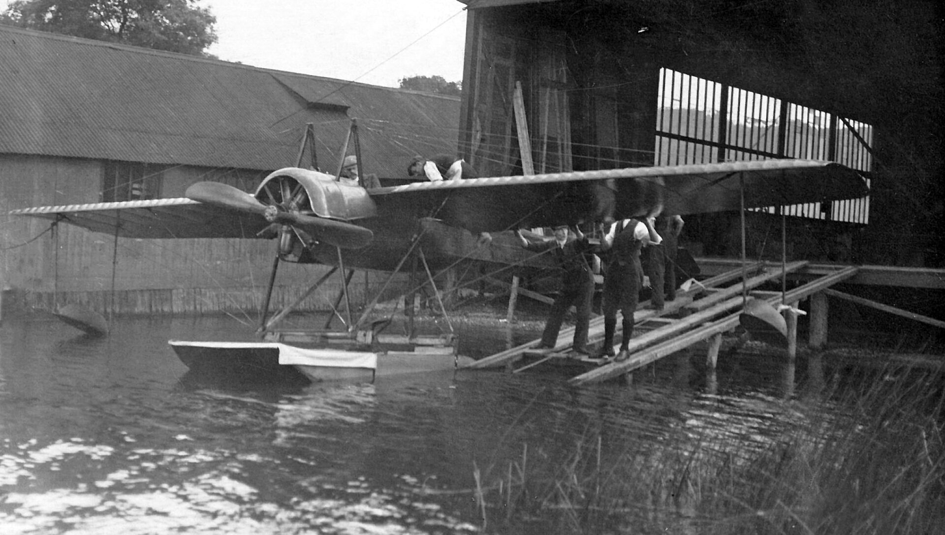
On 25 November 1911, at Windermere, Waterbird became the first hydro-aeroplane outside of France and the USA to take off and alight successfully on water. A telegram from the pilot Herbert Stanley Adams confirmed the initial flights and that no damage was sustained.
It was the world’s first successful flight to use to use a ‘stepped’ float, which was patented by Edward Wakefield. The dimensions of 12 feet long, 2 feet wide and and 12 inches deep followed those by Glenn Curtiss: this photograph was taken just before take-off.
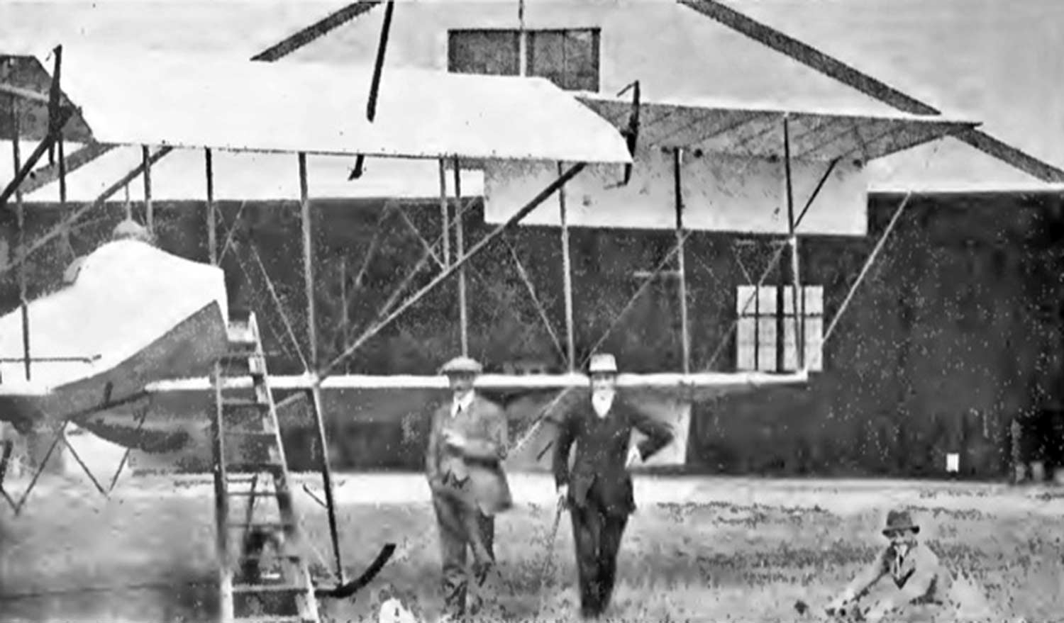
Waterbird was an Avro Curtiss-type, built to the order of Wakefield by A. V. Roe & Company (‘Avro’) at Brownsfield Mills, Manchester.
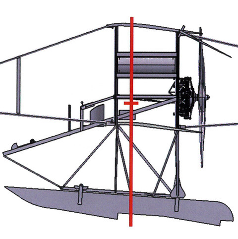
Centre of Gravity
Upon transfer to Brooklands on 25 May 1911 for testing, alterations included extension of the upper wings, the ailerons were disconnected and smaller straight trailing edge ailerons were added. Therefore, the original ailerons with semi-circular trailing edges became the inner ailerons, and serve as part of the wing once enough forward speed has been achieved so as to raise them. The outer ailerons are operated by a stick controlled by the pilot’s hand, whereas Curtiss used the system of a brace fitted to the pilot’s shoulders and controlled by movement of his body.
Delivery to Windermere took place on 7 July.
Wakefield carried out a long series of experiments with floats of many shapes and sizes, weighted with sandbags to represent the conditions of the aeroplane with pilot, which were towed by a motor boat.
Nevertheless, as reported by Lieutenant Arthur Longmore ‘The machine with the engine stopped is inclined to trim by the tail so that at present if the engine stops whilst on the water the pilot must step out and stand at the bows of the hydroplane’. Also, when emerging from the hangar and manoeuvring, whilst if under tow then the pilot had to sit forward.
‘My object has been from the first to eliminate every source of danger in flying that could be eliminated. I claim to have succeeded so far.’ – Letter from Wakefield to Flight magazine, 11 January 1912.
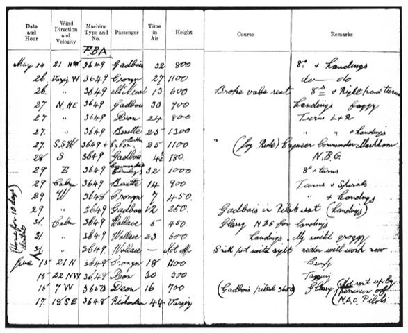
By 25 January 1912, Waterbird had made about 60 flights on 38 different days. – The Aeroplane magazine.
It was noted that Adams had found difficulty in judging height when landing on still water. – The Aeroplane magazine, 13 and 20 June 1912. That is, ‘In a breeze the ripples give a measure of distance, but on still water one sees considerably below the surface.’ This condition is known as ‘glassy water’, and was recorded by instructor Henry Reid in a log book entry for 15 June 1916.
The best way to deal with glassy water was described by Clifford Fleming-Williams ‘Slow the engine so that the machine continues to travel on an even keel but is slightly dropping all the time, and thus feel your way down’. Also, that newspapers were dropped by boat, ‘which floating on the water made it easier for the pilot to judge the surface’. – The Royal magazine, January 1916.
‘Waterbird provided the vital springboard to establishing a twin centre of technical innovation and flying expertise.’ – Navy Wings.
In that Wakefield’s seaplanes did not exceed 70 mph and were very stable, then they were themselves not suitable for offensive military purposes. Rather, he envisaged use for costal defence and military scouting.
ENGINES
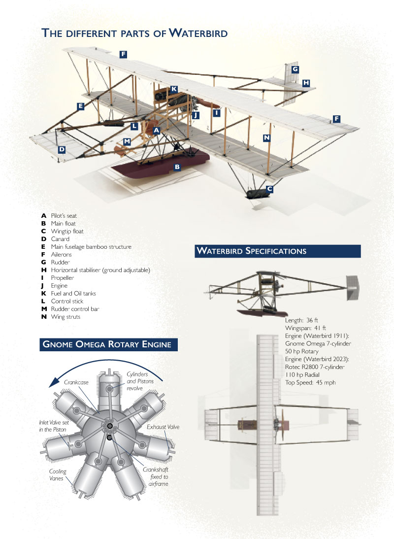
Waterbird had a 7-cylinder 50 horse power Gnome, the lightest engine per horse power then on the market, judging it on its rating by cylinder capacity. As a rotary engine, the cylinders revolved as did the crankcase, upon which the propeller was mounted, around a stationary crankshaft – please see the above Gnome diagram. The Gnome engine had been designed in 1907, patented and built in 1908 and established as a success by mid-1909. Neither an Avro nor a Curtiss had previously flown with a Gnome. The engine was mounted at the rear, behind the propeller [a ‘pusher’].
One reason for a pusher configuration can be appreciated from comparison with the experience of operating an Avro D at Barrow-in-Furness, which had its engine mounted at the front behind the propeller [a ‘tractor’]. The commander at Barrow, Captain (later Rear Admiral Sir, CB) Murray Sueter, noted in a Report published in the Royal Aircraft Factory Reports and Memoranda of December 1911 ‘The slightest spray striking [the propeller] will score the leading edge of the blades and eventually break them’. Another reason for the engine being behind the pilot is that the Gnome engine’s lubrication system was ‘total-loss’ i.e. in excess of 2 gallons per hour of oil was sprayed into the air, but castor oil is a laxative!
‘The 50hp Gnome can be considered as the archetypal aeronautical rotary…. It was credited with being the first to be able to run for 10 hours between overhauls…. Castor oil was the natural choice for rotary engines because it was (and still is) a superb lubricant, and was unquestionably superior to the mineral oils then available.’ – The Rotary Aero Engine by A Nahum.
‘The advantage that castor oil possesses as a lubricant for rotary engines is due to its volatility, for before it has time to accumulate on such vital parts as the sparking-plug points, it evaporates and the hard flake-like deposit it leaves behind is blown out by the scavenging action of the exhaust.’ – Flight magazine, 28 October 1911.
There is a surviving 1911 Gnome pusher engine at Tatton Park, Knutsford. It was owned by Major the Honourable Maurice Egerton, the last Baron Egerton, who was granted Aviator’s Certificate No. 11 and had a Short-built Wright Flyer.
Egerton built a hangar on the Aero Club’s first aerodrome at the Isle of Sheppey, Kent which opened in February 1909. Following the start of operations at Eastchurch in January 1910, he had his aeroplane and hangar moved across there. The first 4 officers were taught to fly at Eastchurch and by 1 September 1911 had completed the stipulated 6 months’ training course, prior to which Egerton acted as their test pilot. This photo is of Egerton’s Short aeroplane and those officers, far right is Longmore. – The Aeroplane magazine, 7 September 1911.
‘At the Curtiss Company’s works [at Hammondsport, New York] we placed a very able inspector and one of the first to gain his pilot’s certificate in this country, Lieutenant Commander Maurice Egerton. All the data which we gained in actual flying experience in the North Sea we passed through Egerton to the Curtiss Co. Consequently, that firm were well up to date when America came into the war.’ – Airmen or Noahs by Sueter.
The only known surviving engine to have been operated at Windermere is the Clerget 4 V which powered Gnosspelius No. 2.
WATERBIRD’S WRITE-OFF
At about 9:45 pm on 29 March 1912, the hangar collapsed at Cockshott, which housed Waterbird and also Waterhen which had not been completed. Since none of the other numerous wooden structures in the vicinity were damaged, it would appear that the builders of the hangar had failed to secure it adequately to the wooden piles. Such was the strength of the wind, that the hangar was lifted into the air and carried a few yards so as to collapse in a tangled heap of wood and metal – the hangar’s location can be orientated by reference to the domed house on Bell Isle which is visible on this photo.
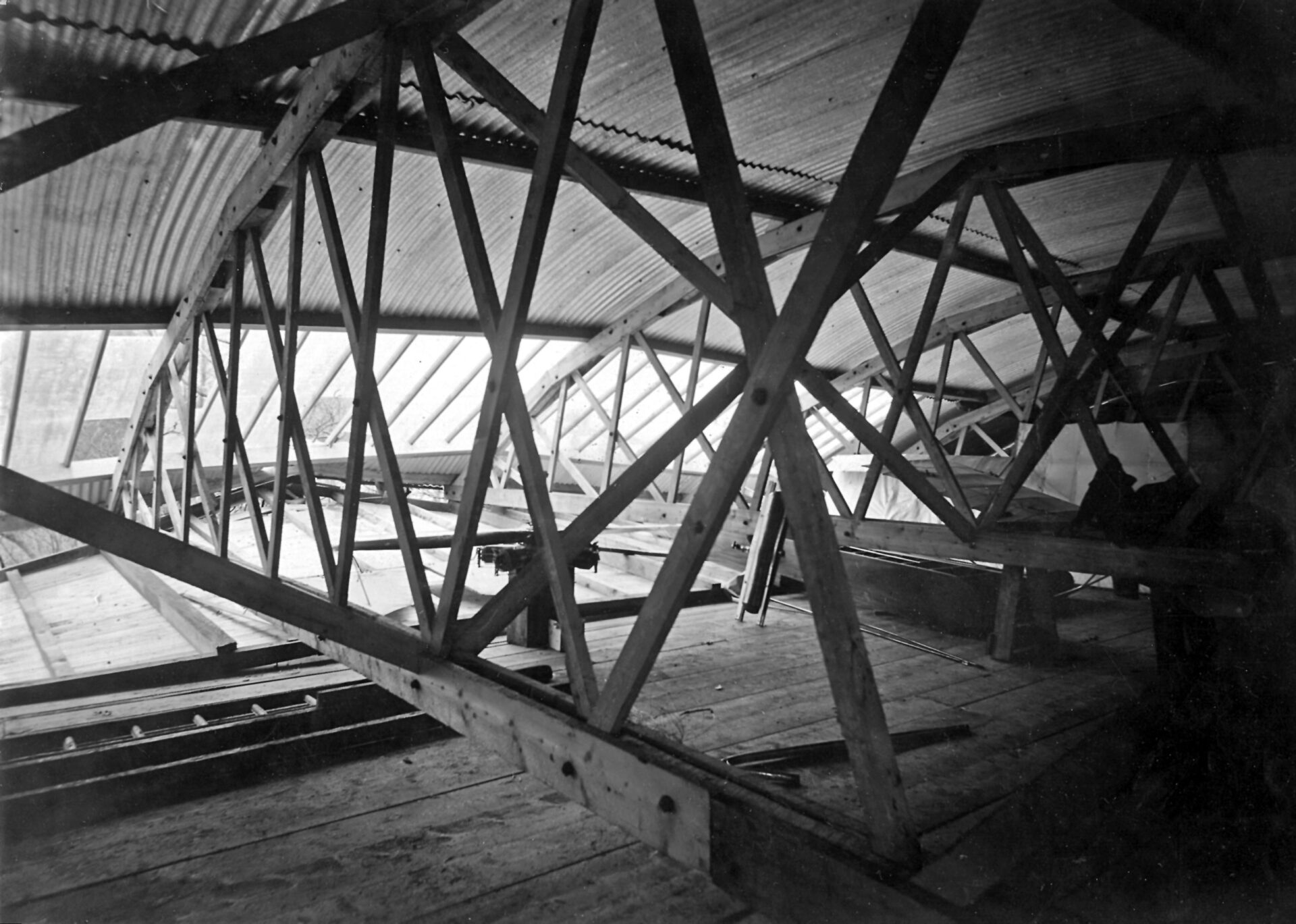
Whilst the splintered spars and torn fabric of the starboard mainplanes of Waterbird protruded from the hangar’s truss, the canard, centre section structure of wing, and port lower wingtip section, plus a stringer from the centre section, the engine (which lived on in the Avro Duigan/ Seabird), tank, and the main float all survived. Albeit that falling beams had crushed the mainplanes, the curvature of the Belfast-pattern corrugated iron roof gave some protection.
Firstly, a photo includes the engine, albeit with only 1 propeller blade, placed upon an upturned box, a tank propped against a beam and the float placed behind the tank at an angle of 90 degrees, with other surviving elements of Waterbird in the background. Secondly, this photo at the re-erected hangar (Note the internal and external shoring) depicts damaged Waterbird’s wings and a new rudder leaning against the rear gable, bamboo outriggers on the floor by the side wall and sections of wing being built.
THE SURVIVING RUDDER
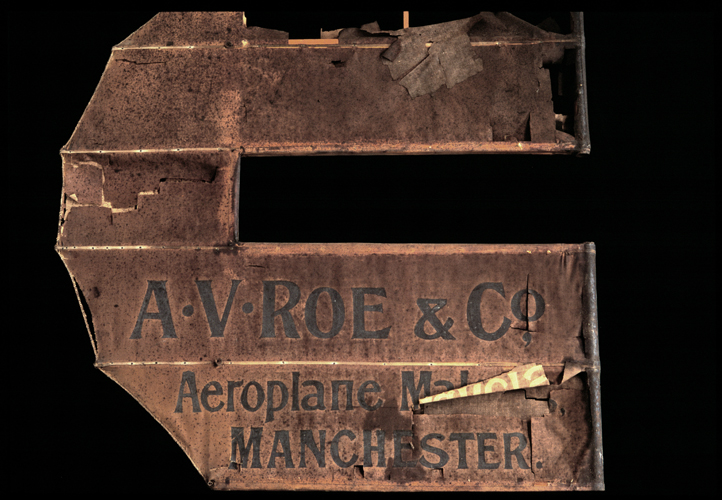
Here is a photo of the surviving rudder.
The rudder broadly follows the design of the original drawing.
By contrasting with photos taken at Windermere, it is apparent that a different rudder was used there. That is, the original design had 2 panels above and below the cut-out for the horizontal tail. However, these photos show that additional ribs have been added so as to create another panel above and below the cut-out.
The rudder made by Avro at Manchester was changed following flight-testing at Brooklands. Whilst built to Curtiss dimensions, it was considered to be too small.
So, it follows that this rudder is actually the first one from Manchester, particularly with the extent of Avro lettering which was absent at Windermere.
– This rudder is the oldest surviving part to carry the wording of A. V. Roe & Co.
PHOTOS OF WATERBIRD
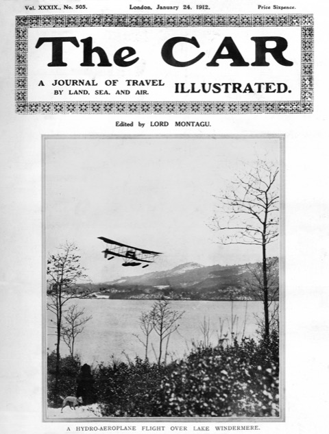
There are 20 known photographs of Waterbird. 3 of them were made into postcards by Herbert & Sons [the first is the same as ‘FLYING’ below and the second as ‘ALIGHTING’ below] and 1 by Avro attributed to the Manchester Guardian in which it appeared on 19 January 1912 but actually taken by Frank Herbert [the same as on the front pages of The Car and The Aero magazines and also in Le Plein Air magazine], whilst FLYING was also included in a 1911 Christmas card from Wakefield. This photograph was in The Daily Sketch, 20 January 1912, attributed as a Daily Sketch Photograph and also in the Sunday Chronicle, 28 January 1912, attributed as a “Sunday Chronicle” photo!
Wakefield ‘presented to the Royal Aero Club a collection of lantern slides depicting his hydro-aeroplanes at Windermere’. – Flight magazine, 27 April, 1912.
Lantern slides of Waterbird have been digitised:-
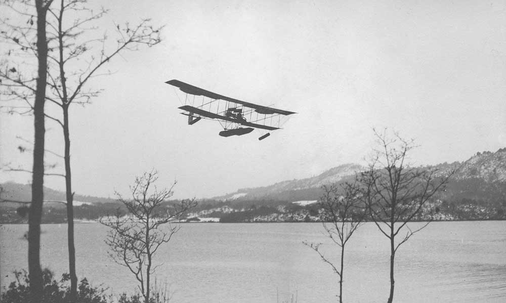
FLYING 2 (on the front page of Flight magazine)
ALIGHTING (on the front page of The Aeroplane magazine).

There were considerable skills at Windermere in that Waterhen, Waterbird’s successor which first flew on 30 April 1912, was constructed locally by Borwick & Sons. The float was much broader at 6 feet with a single step and sheer at the bow, so as to enable Waterhen to be capable of carrying a passenger. The shortness of the timescale to the first flight indicates that mainplane sections, incorporating ailerons designed with straight trailing edges and increased camber, must already have been under construction for Waterbird.
It may therefore be concluded that ‘this photo’ above – under ‘WATERBIRD’S WRITE-OFF’ – is of the build of Waterhen. Waterhen was the most successful Windermere-built seaplane, the last known flight being on 16 August 1916 when Edward Haller became the final pupil to pass the tests for his Aviator’s Certificate.
A photo of the hangar at Cockshott, with the Deperdussin, includes stacked sections of bamboo for the outriggers of Waterhen. It also shows the addition of a ‘skirt’ to the port side of the float, probably to counter propeller torque.
DIFFERENCES BETWEEN THE REPLICA WATERBIRD AND THE ORIGINAL
Trials of the replica Waterbird were carried out at Windermere without any publicity. ‘The public should not misunderstand the attitude we have taken to keep away curious onlookers just for the present. It was not the desire to mystify people, or to keep secret anything, but simply to give us an opportunity to go-on with the work which I have mapped out without being an object of curiosity.’ – Glenn Curtiss in the San Diego Union newspaper, 25 January 1911.
The original had a second-hand 7-cylinder 50hp Gnome rotary engine: the replica has a new 7-cylinder 110hp Rotec radial engine.
The replica’s propeller is bespoke, created by computer-controlled machinery. Engine to propeller speed is reduced by a ratio of 3:2.
On the original, the outer ailerons rose with airflow and were pulled downwards by wires from the control stick, but a downgoing aileron would have produced significant drag on that side: on the replica, for safety reasons there is a closed circuit – each moves by a balance cable in the opposite direction to the other, so as to counter adverse yaw. (The stick also controls the canard; the inner ailerons are not controlled.)
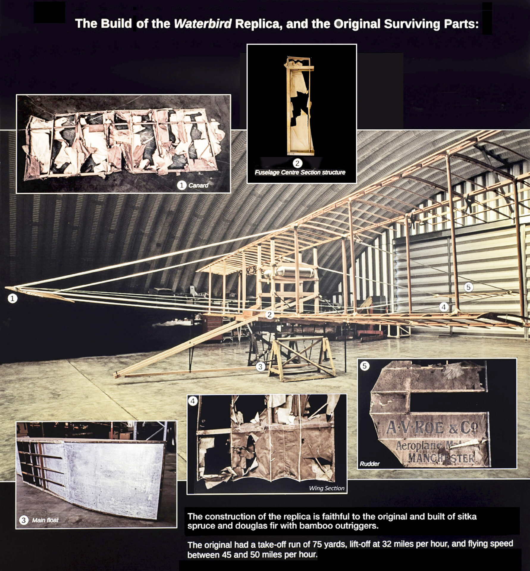
The original’s wing spars were made of spruce: on the replica, they are made of Douglas fir, which has higher strength properties, as are struts between the wings.
The fuselage parts on the original were made of hickory: on the replica they are made of ash which is lighter and more durable.
The replica’s spars run the entire length of the upper wings: on the original, the upper wings were later extended by almost 6 feet. Copper nails and roves were used on the original’s spar webs: on the replica, they are screwed and glued.
The replica has the benefit of 8 coats of modern dopes and Diatex polyester yarn sewn in place, with seaplane resin eyelets for drainage: in contrast to the use of tacks and double-surfaced Pegamoid cloth on the original. GB Patent No. 19,710 of 1891 by Frederick Annison and US Patent No. 771,257 of 1904 by William Mackintosh were licensed to New Pegamoid Ltd. Curtiss wings were covered on the upper side with Goodyear fabric No. 10, the same as used by the Wright brothers, and, on the lower, by a fine cotton sail cloth. The cloth was not laced as formerly, but tacked to the main ribs.
For the construction of the airframe, the replica has:-
modern glues, with glue applied where it was not originally used;
certified bracing wires (it is diamond braced, with flying, landing and incidence wires), and
a study on load testing of types of bamboo, in comparison to aluminium and ash, which was used again for the outriggers.
The main float of the replica has:-
the design features of the original, including a 22 gauge aluminium floor which was cutting edge technology for the time, but now improved with 2 full length aluminium stiffeners and 4 in each step, applying modern techniques and methods of analysis;
increased structural integrity;
increased buoyancy of 109% in excess of the buoyancy required to support the maximum weight of the complete aeroplane – the minimum current regulatory requirement is 80%: 14 Code of Federal Regulations 23.751 and Certification Specifications for Very Light Aeroplanes 757, and
5 watertight compartments, which would provide flotation in the event of damage.
The auxiliary inflated wingtip floats, originally known locally as ‘Wakefield sausages’, now are rigid and have 3 watertight compartments.
The original did not have any instruments fitted. (Height and speed instruments were tested on Waterhen. – The Aeroplane magazine, 16 October 1913.) The replica has a simple Hall airspeed indicator, plus a volt meter and engine instruments.
On the replica, wool telltales on the canard give an indication of stall and a yaw string shows slip or skid. During the first flight through a complete circle by Wilbur Wright near Dayton, Ohio on 20 September 1905, he ‘became the first aviator to mistake wind drift for a sideslip. … He tied a piece of string to the front elevator for a slip indicator and, on the next attempt, seeing that the string blew straight backward, he realized that the wind drift had simply created an optical illusion’. – Famous Flyers and the Ships They Flew by D Dwiggins.
Computer modelling enabled the gathering of data and verification of the overall replica aeroplane’s design, leading to some bracing wires being replaced with steel tubes, and additional tubes installed.
Photos during the replica build (Note the aluminium outriggers prior to the change to bamboo) and of surviving parts are here.
Any hairline splits in bamboo can be repaired quickly by abrading the surface with sandpaper, wrapping with Kevlar or polyester thread and soaking in cyanoacrylate adhesive.
FOR AN INTERACTIVE 3D MODEL OF THE REPLICA WATERBIRD, click here
PILOT’S REPORTS
For a Pilot Report on the original Waterbird, click here
For a Pilot Report on the replica Waterbird, click here
GREAT BRITAIN PATENTS
Obtained by Edward Wakefield
The means for attachment of a float to an aeroplane and a ‘stepped’ float. On 11 December 1911, through agents Arthur Edwards & Co. Ltd. of London, Wakefield submitted Patents No. 27,770 and No. 27,771 to the Patent Office which were granted respectively on 12 September 1912 and 18 March 1913. The objects of the inventions were to ‘prevent jar when rising from and alighting upon the water, and to provide an attachment of such a character that when the hydroplane is upon the water the aeroplane is suspended therefrom’; and to ‘provide an aeroplane with means for enabling it to alight, float and travel along the surface of water and to rise again therefrom’. The method of attachment included looped rubber rings, to act as shock absorbers [bungees, at low cost, weight and complexity].
Wakefield’s application for a patent for a stepped float i.e. 27,771 was opposed by The British & Colonial Aeroplane Co Ltd (‘Bristol’) on the ground that the nature of the invention was not sufficiently or fairly described and ascertained in the complete Specification. The Hearing was before H Hatfield on 7 March 1913, when Wakefield, who had qualified as a Barrister, represented himself. Wakefield wrote ‘The Comptroller at the close intimated that he would deliver a written judgment, but he added that it would be in my favour with costs’. The Decision was that a patent would be sealed, Wakefield having carried out considerable experiment and for the first time combined features of construction in a novel way.
A float of a seaplane which supported its own weight or the greater part of such weight during flight. On 13 November 1913, Wakefield obtained Patent No. 18,051.
Also, Wakefield wrote an article on the principles of flying from water, which was published in The Aeroplane magazine, 10 April 1913: click here to view the article.
Obtained by Oscar Gnosspelius
In July 1910, Gnosspelius had floats built with a step, but did not protect that work.
A concave and V shaped float, in a move away from the flat bottom of initial floats. On 12 February 1914, Gnosspelius obtained Patent No. 10,801; which construction is used on every seaplane float today.
On 2 August 1923, Patent No. 192,568 was obtained by Gnosspelius, Eustace Short, Oswald Short and Arthur Gouge for a similar step in the upper surface of a lifting aerofoil. Such a step was applied to the upper wing of the Gull aeroplane designed by Gnosspelius, which was first flown on 26 May 1923.
Obtained by Alliott Verdon Roe
The world’s first control column – ‘stick’ – for which Roe obtained Patent No. 26,099 on 14 November 1907. Like the Wright Flyer, which first flew 8 years beforehand, and the Roe I Biplane of 3 years earlier, Waterbird is a biplane with pitch control by way of a forward-mounted, pivoting canard, albeit the Wright Flyer had a bicanard. The single control column differed from the Wright design which had a lever for each hand, and from the control wheel used by Glenn Curtiss. The connection from Waterbird’s stick to the canard is by way of a Farman-type pole. – The replica Waterbird has a closed circuit of wires, pulleys and horns for the outer ailerons.
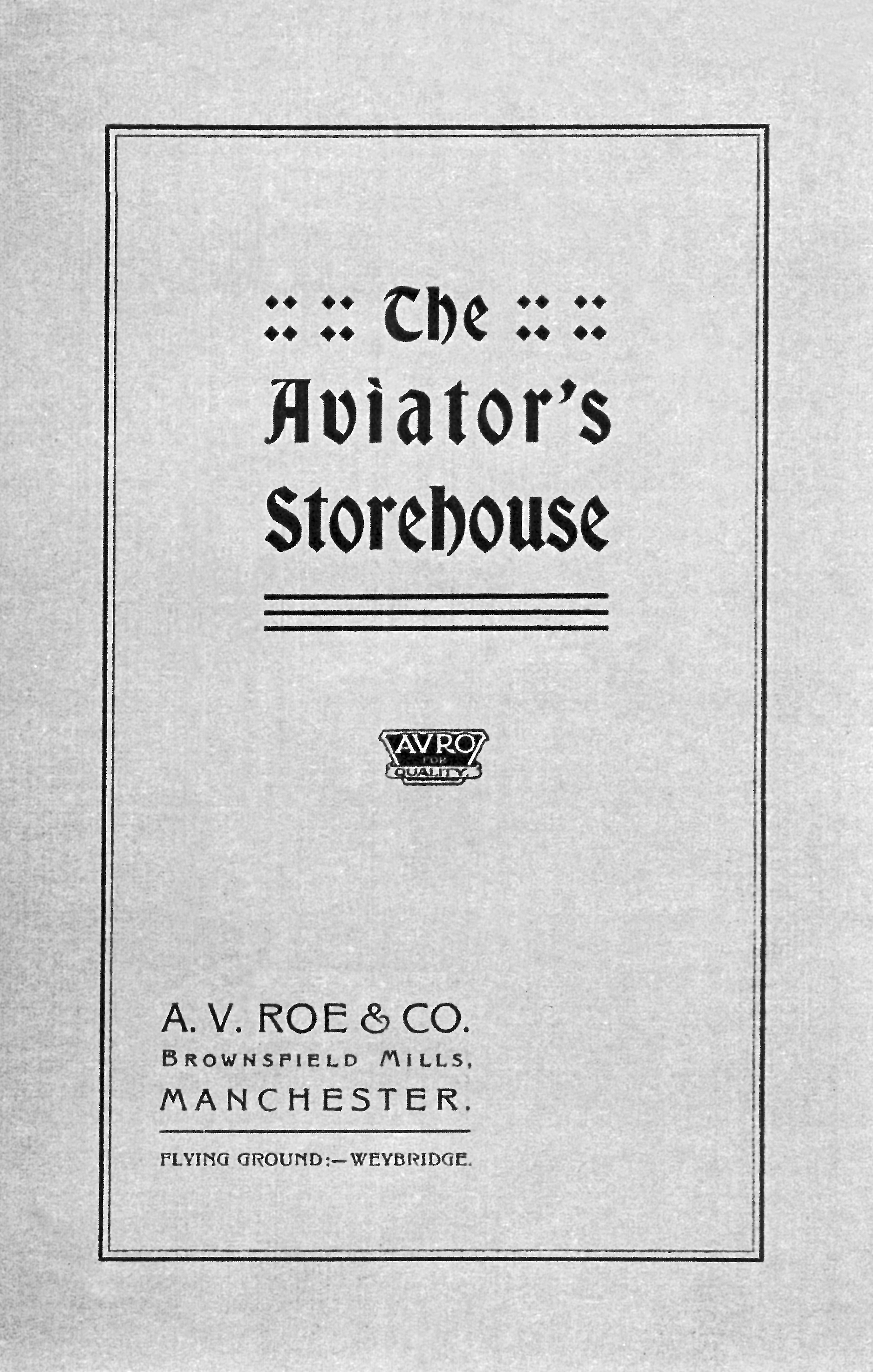
The turnbuckle, for which Roe obtained Patent No. 17,740 on 30 March 1916. The Roe 1 included turnbuckles, being of a simple home-made type. Turnbuckles, initially known as strainers, were marketed by Avro through their Aviator’s Storehouse. For customers who ‘want stuff in a hurry’, ‘Practically everything in the list has a telegraphic code word attached, so that quotations can be procured or goods delivered at the very shortest notice’. – The Aeroplane magazine, 8 June 1911. Products included bamboo, fabrics, propellers, shock absorbers and wood. Marketing was ultimately by the Aircraft Supplies Company Ltd as sole selling agents. Supplies of Admiralty, A.G.S. and Binet types of turnbuckles were not equal to demand, whereas Avro increased output such that it made an annual £40,000 profit on turnbuckles alone for a number of years in and subsequent to World War 1. – The replica Waterbird has an estimated 250 turnbuckles.
The Aeroplane magazine, 28 February 1917.
The Aeroplane magazine, 14 March 1917.
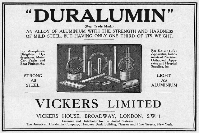
An Inventory of the assets belonging to the Lakes Flying Company, a schedule to the Partnership Deed dated 20 December 1911 with Adams, included ½ dozen sundry pieces aluminium and Duralumin.
In his Report, dated 20 January 1912, Longmore stated that a new float under construction was intended to be fitted to Waterbird with a duralumin floor; but this did not happen.
However, the float of Waterhen was described in Flight magazine, 7 December 1912 as having duralumin sides.
‘ … For the change in the official attitude towards duralumin as an aircraft material, Short Brothers, of Rochester, one of the pioneer aircraft firms in Great Britain, can claim a good deal of credit. … On the design side we were privileged to inspect the large water tank, the equivalent to the Froude tank at Teddington, which Mr. Oswald Short had built some two years ago.’ – Flight magazine, 11 March 1926.
It is considered that aluminium and duralumin were used in hydro-aeroplane floats at Windermere due to information derived from airship construction by Vickers Ltd at Barrow. Duralumin became “Vickers’ Duralumin” (Registered Trade Mark).
ASSETS
The Inventory dated 20 December 1911 commences with the major assets of the Lakes Flying Company, including Waterbird.
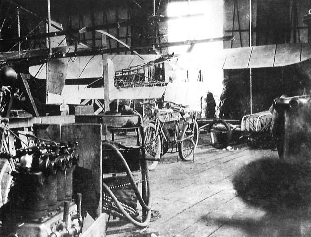
This photo was taken inside the Cockshott hangar in 1915 and shows not only the Blériot seaplane, but also at top left an uncovered port wing of Waterhen adjacent to its rudder, at bottom left the ex-Gnosspelius No. 2’s Clerget engine and underneath the Blériot’s starboard wing a partially assembled float for the Blackburn Improved Type 1. Behind the engine is a mobile forge and what appears to be a gas generator.